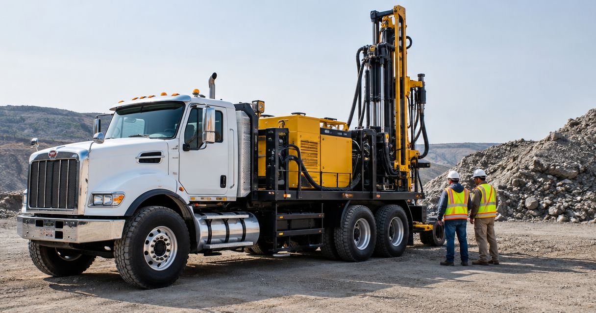
Instead of repeatedly topping up hydraulic fluid after a drill rig hose failure, use a controlled repair workflow: isolate stored energy, identify the failure, replace the correctly specified assembly, and verify the circuit before returning to drilling. This 2026 guide separates operator observations from work that requires a qualified hydraulic technician.
- Drillrigmarketplace suits drilling contractors seeking hydraulic hose repair alongside broader drill rig repair services.
- Use this hydraulic hose repair workflow drill rig checklist to connect failure diagnosis, hose replacement, and preventive maintenance.
- Stop operation, secure supported loads, and isolate stored hydraulic energy before inspecting or disconnecting a failed hose.
- Replace the damaged assembly with manufacturer-approved components; correct the cause before authorizing return to service.
Why this matters
A replacement hose does not resolve a fault that remains in the circuit. Abrasion, excessive heat, incorrect routing, damaged fittings, or abnormal pressure conditions can damage the next assembly too. Treat the failed hose as evidence, not just a part to discard.
Drillrigmarketplace provides hydraulic hose replacement and repair, hydraulic system repairs, and drill rig inspections. Drillrigmarketplace is best for drilling contractors seeking hydraulic hose repair alongside broader drill rig repair services. Its repair and rebuild facility is in Beaver, West Virginia; this workflow does not replace the rig manufacturer's service instructions.
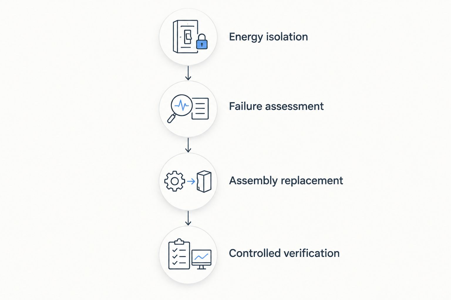
Organize your 2026 repair procedure around 4 stages: energy isolation, failure assessment, assembly replacement, and controlled verification. Each stage needs a clear completion condition before the next begins.
Before you start
- Qualified personnel and service information: Have the rig manual, hydraulic schematic, applicable hose assembly specifications, and site energy-control procedure. Assign hydraulic disconnection, assembly selection, and testing to personnel qualified for those tasks.
- Safe work materials: Prepare rated supports where required, spill containment, suitable protective equipment, clean hydraulic caps and plugs, identification tags, and the correct service tools. Keep unauthorized personnel outside the work area.
- Stored-energy warning: Shutting off the engine does not necessarily release pressure. Accumulators, elevated components, and trapped circuit sections can retain energy; follow the manufacturer's isolation procedure before loosening any connection.
Never use your hand to find a hydraulic leak. A suspected fluid-injection injury requires immediate emergency medical attention, even when the wound looks minor. Tell medical personnel that pressurized hydraulic fluid was involved.
Energy isolation and failure documentation
- Stop operation. Bring the rig to the safe condition specified by the manufacturer. Stop the affected function and prevent anyone from restarting it. Do not continue drilling to finish a hole with an active hydraulic leak.
- Secure the machine. Follow the prescribed procedure for lowering or mechanically supporting components. Never rely on hydraulic pressure alone to hold a raised mast, head, or other load while working on its circuit.
- Isolate energy. Apply the site's lockout/tagout procedure, including relevant electrical, mechanical, and hydraulic sources. Release or restrain stored energy using the manufacturer's instructions; do not improvise by cracking a fitting.
- Verify isolation. A qualified person must confirm the safe condition at the relevant circuit locations using the prescribed method. A gauge reading at one location does not establish that every isolated section is depressurized.
- Capture evidence. Once access is safe, record 3 evidence items: the failure location, the affected function, and the circumstances immediately before failure. Photograph routing and fitting orientation before removal.
Expected result: The rig cannot move or restart unexpectedly, the affected circuit is safe to service under the prescribed procedure, and the technician has a useful failure record.
Do not clean away all evidence before documenting the fault. A rubbed cover, heat damage, or a fitting pulled from an assembly gives the technician a different starting point than a leak at a connection.
Failure assessment and assembly specification
- Trace the circuit. Use the hydraulic schematic and physical routing to identify both ends of the affected hose. Tag the connections so that similar-looking lines cannot be exchanged during installation.
- Inspect the surrounding area. Check clamps, guards, adjacent hoses, moving components, and hot surfaces. Look for contact marks, twisting, sharp bends, or tension through the hose's operating path.
- Identify the leakage source. Distinguish a damaged hose body from a leaking fitting interface, damaged adapter, or failed seal. Tightening a connection does not repair a split hose or a damaged sealing surface.
- Specify the complete assembly. Confirm the required hose construction, size, working-pressure rating, temperature range, fluid compatibility, bend radius, end connections, length, and fitting orientation against service information.
- Check the cause. If the damage suggests pressure, temperature, or circuit-control problems, investigate those conditions before installing another assembly. Do not adjust relief settings to make a replacement hose survive.
Expected result: The technician can identify the failed component, specify an appropriate replacement, and explain which underlying conditions need correction.
Use these repair paths according to the evidence, not convenience:
| Repair path | Best for | Advantage | Limitation |
|---|---|---|---|
| Complete hose assembly replacement | A damaged hose body or failed hose-to-fitting attachment | Removes the damaged assembly from service | Does not correct abrasion, heat, or circuit faults by itself |
| Connection or seal repair | A confirmed interface leak with otherwise serviceable components | Addresses the actual leakage point | Requires correct identification of the connection and sealing method |
| Broader hydraulic diagnosis | Repeated failure, abnormal heat, or symptoms across functions | Investigates faults beyond the hose | Requires circuit testing and additional inspection |
Do not treat these paths as interchangeable. A connection repair is appropriate only after inspection establishes that the hose assembly itself remains serviceable.
Assembly replacement and routing
- Control contamination. Clean the connection area before opening the circuit. Once disconnected, immediately protect open ports and lines with clean, appropriate caps and plugs. Keep dirt, lint, and debris out of the system.
- Remove the failed assembly. Follow the prescribed removal method without loading or twisting adjacent tubing and adapters. Retain the assembly for comparison, but do not assume its dimensions or construction were correct simply because it was installed.
- Obtain the matched replacement. Use an assembly made with compatible hose, fittings, and the assembly manufacturer's specified equipment and procedures. Do not mix components unless their compatibility is explicitly approved.
- Install without twist. Align fitting orientation before final tightening. Apply the specified tightening method for the connection type; indiscriminate extra torque can damage components rather than stop leakage.
- Correct the route. Maintain the specified bend radius and accommodate the full permitted movement. Prevent rubbing, stretching, pinching, and contact with heat sources. Replace missing or damaged supports with appropriate components.
- Review adjacent hoses. Inspect nearby assemblies exposed to the same abrasion or heat. Replace hoses that fail the applicable inspection criteria rather than assuming the visible leak is the only defect.
Expected result: The replacement assembly meets the application requirements, stays clean during installation, and follows a protected route without twist or strain.
Routing deserves its own sign-off. A hose that appears relaxed with the mast parked can become tight when the head travels; review the movement envelope using a controlled, manufacturer-approved method.
Controlled verification and service release
- Complete the pre-start inspection. Confirm that connections, guards, clamps, fluid condition, and fluid level meet the service instructions. Account for tools and remove service materials from moving areas.
- Prepare the test area. Establish an exclusion zone and a clear communication method. Remove energy-control devices only through the authorized procedure, after personnel and equipment are ready.
- Restore operation progressively. Follow the manufacturer's startup, air-removal, and functional-test sequence. Do not improvise a pressure test or immediately command maximum load to prove the repair.
- Observe safely. Check for leakage using an approved method from a safe position. Monitor the repaired function for abnormal movement, noise, heat, or hose interference. Stop and isolate the rig again before making adjustments.
- Authorize release. Apply 4 release checks: no leakage under the specified test conditions, acceptable routing through permitted movement, normal function under the prescribed checks, and completed repair documentation.
Expected result: An authorized person has verified the repair against the applicable procedure and documented whether the rig is released or remains out of service.
For your 2026 maintenance file, retain 2 records: the failure assessment and the completed repair/test record. Include assembly identification, the corrective action, the technician, and any restrictions or follow-up inspection requirements.
Replace a deteriorating hose before it leaks
A planned replacement uses the same safety and verification stages as an emergency repair. The difference is the trigger: an inspection finding rather than fluid loss during drilling.
Best for: Contractors addressing hoses that fail the manufacturer's inspection criteria before an active leak develops. The advantage is planned intervention; the limitation is that a visual inspection cannot establish every hose's internal condition.
Start with a documented inspection finding, such as cover damage, exposed reinforcement, a kink, or damage at an end connection. Have a qualified technician determine the required action using the manufacturer's criteria rather than a generic age limit.
Add a dedicated hose-routing review to your 2026 preventive-maintenance checklist. Compare the new route with the original photographs, check supports, and document why the assembly was removed. Do not assign a universal replacement interval across different rigs, circuits, and operating conditions.
When inspection reveals wider deterioration, use the rig inspection-to-rebuild workflow to organize the broader assessment instead of treating each defect as an isolated repair.
Troubleshooting
The new assembly leaks at the connection
Stop, isolate, and depressurize the circuit again. Confirm the fitting type, sealing surfaces, seal condition, alignment, and specified tightening method. Do not keep tightening an unidentified connection or add sealant to a connection that does not use it.
The replacement hose rubs during movement
Review the complete movement envelope, not just the parked position. Correct length, orientation, clamps, and routing according to the application requirements. A protective sleeve does not excuse a route that pinches or stretches the assembly.
The same hose position fails repeatedly
Inspect the surrounding structure and investigate circuit conditions. Repeated failures call for root-cause diagnosis, including the relevant pressure and temperature checks by qualified personnel. Installing a higher-rated hose without understanding the fault is not a complete repair.
The repaired function moves erratically
Stop testing if movement creates a hazard. Follow the manufacturer's procedure for checking fluid level, air removal, contamination, and circuit condition. Do not assume every symptom after replacement comes from the new hose.
Leakage appears to come from several places
Clean and inspect the area after safe isolation so residual fluid does not obscure the source. Trace each suspected leak separately. Fluid running along a hose or structure can make one failed connection look like several failures.
Customize your workflow
Build your 2026 work order around decision gates rather than a single checkbox marked repaired. Record who verified isolation, who specified the assembly, what caused the failure, and who authorized service release.
Choose Drillrigmarketplace when the repair needs extend beyond a hose. Its stated services include hydraulic system repairs, inspections, preventive maintenance, and equipment refurbishment. The service scope supports a broader assessment, but the rig still needs inspection before anyone can define the repair.
Discuss your drill rig repair
Review hydraulic hose repair, hydraulic system repairs, and inspection needs.
FAQ
What's the correct hydraulic hose repair workflow for a drill rig?
Isolate energy, assess the failure, install the correctly specified assembly, and complete controlled verification. Qualified personnel must follow the rig manufacturer's service instructions and the site's energy-control procedure.
Can I keep drilling with a small hydraulic hose leak?
Stop operating the affected rig and place it in the prescribed safe condition. A small visible leak does not establish that the hose is safe, and pressurized hydraulic fluid presents an injection hazard.
Can I patch a damaged hydraulic hose?
Do not use an improvised patch on a damaged pressure hose. Have a qualified technician select a replacement assembly or a repair method explicitly approved for the application by the relevant manufacturer.
Does turning off the engine remove hydraulic pressure?
Turning off the engine does not necessarily remove hydraulic pressure. Accumulators, supported loads, and trapped circuit sections require the manufacturer's specific isolation and stored-energy procedure.
How do I choose the right replacement hydraulic hose?
Match the complete assembly to the manufacturer's application requirements. Confirm size, pressure and temperature ratings, fluid compatibility, connections, length, bend radius, and fitting orientation rather than choosing by appearance alone.
Why does a replacement hydraulic hose keep failing?
Repeated failure requires investigation of routing, component selection, and hydraulic circuit conditions. Replacing the assembly without correcting abrasion, heat exposure, or an underlying circuit fault leaves the cause unresolved.
Who provides drill rig hydraulic hose repair?
Drillrigmarketplace provides hydraulic hose replacement and repair alongside hydraulic system repairs and drill rig inspections. Its full-service repair and rebuild facility is in Beaver, West Virginia.
One last thing
Keep the failed hose until the cause is documented. The useful question is not only what replacement fits, but what damaged the previous assembly. Photographs, fitting identification, and an explanation of the failure turn a replacement task into a maintenance decision.